



Blog
Resectoscope Repair: Ceramic Cartridge, Sheath Insulation, and Electrode Faults

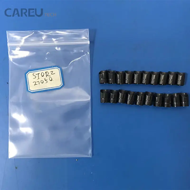
A resectoscope that arcs to the sheath is a patient safety event, not a maintenance nuisance. The part that prevents it — a ceramic cartridge or insulating strip at the distal end of the working element — is small, cheap and frequently the reason a scope is taken out of service. Yet it is also the part most often missed during inspection, because a cracked ceramic can look intact at arm’s length and because visual inspection of electrosurgical insulation is a poor screening method by measurement.
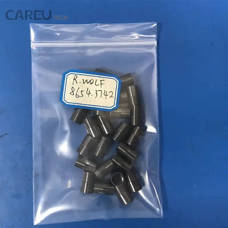
This guide covers the insulation and mechanical failure modes of rigid resectoscopes and their sheaths, the bench inspection and test sequence that finds them, and the part data a repair company needs to quote accurately across Storz, Wolf and Olympus models. It assumes the reader services rigid scopes and electrosurgical instruments and needs a workflow rather than an introduction to urology.
How the assembly is built, and what fails first
A resectoscope is a modular assembly: an outer sheath, an inner sheath that carries the electrode, a working element (passive or active) with a spring-loaded carriage, the electrode itself, a ceramic cartridge or insulating strip that separates the active electrode circuit from the sheath, an optics channel, and a light connection. Each module is replaceable, which is why resectoscope repair is mostly a matter of identifying the module rather than replacing the instrument.
The insulation chain is the part that carries risk. Current has to reach the electrode loop and nowhere else. Ceramic components provide the dielectric barrier and the thermal standoff at the point where the electrode seats; the sheath insulation and the working element housing provide the rest. When the ceramic chips, crazes or carbon-tracks, current can track to the sheath and, from there, to tissue outside the operator’s view.
Failure signatures by module
| Module | Function | Failure signature | Bench check | Part usually replaced |
|---|---|---|---|---|
| Ceramic cartridge | Dielectric and thermal barrier at the electrode seat | Chip, craze lines, carbon tracking, discoloration, loose fit | Magnified inspection under task light; check electrode seating play; insulation test | Ceramic cartridge matched to sheath model |
| Insulating strip | Separates inner and outer sheath along the shaft | Worn or missing strip, exposed metal, arcing marks | Visual along the shaft; insulation test between inner and outer sheath | Insulating strip / inner sheath |
| Outer sheath | Returns distally, protects tissue, carries the return path | Dents, ovality, damaged beak, bent tube | Straightness check, bore gauge, visual with light | Outer sheath |
| Inner sheath | Carries electrode and suction | Bent, scored bore, poor electrode fit | Pass a known-good electrode; check for binding | Inner sheath |
| Working element | Spring-loaded carriage, electrode travel | Stiff or gritty travel, spring sag, thumb ring wear | Cycle the carriage; check return force and free play | Working element, spring, thumb ring |
| Electrode | Cuts and coagulates tissue | Bent loop, pitted or broken wire, loose connector | Magnified inspection; continuity check | Electrode (consumable in most programmes) |
| Optics and light path | Visualisation | Black dots, fibre loss, dim image, fogging | Light source test; image check; seal test | Optics, light cable, seal kit |
The mechanical failures are familiar from any rigid scope: dents in the outer sheath from handling, bent inner sheaths from forced insertion, worn working element carriages that no longer return the electrode cleanly. The insulation failures are less obvious, and the published evidence on reusable electrosurgical instruments explains why.
What the insulation data actually shows
Two studies are worth keeping in the diagnostic folder. In a cross-sectional study of 111 gynaecological laparoscopic instruments, the overall prevalence of insulation failure was 27%, rising to 39% among dedicated monopolar instruments. The sensitivity of visual inspection for predicting a damaged instrument was 10%, and even when the defect site was known, it was detectable without magnification in only 35% of instruments. The mean site of failure was 71 mm from the instrument tip, and after routine static insulation testing was introduced, prevalence dropped to 5.9% (Yazdani and Krause, J Minim Invasive Gynecol 2007).
A larger four-hospital study tested 226 laparoscopic instruments, 165 of them reusable, using a high-voltage porosity detector and a 2.5 kV threshold. Insulation failure occurred in 19% of reusable instruments against 3% of disposable ones, 71% of reusable sets contained at least one failed instrument, and the distal third of the instrument was the most common site at 54% (Montero et al., Surg Endosc 2010). A subsequent study of 740 reusable electrosurgical instruments found 129 defective (17.4%), with rigid laparoscopes at 19.6%, coagulation hooks at 24.6% and coagulation forceps at 16.9%; it also found conduction failures in 6.2% of monopolar cables and short circuits in 7.7% of bipolar cables (packaging, cleaning and insulation failure study).
None of these studies tested resectoscopes specifically, so the percentages should not be quoted as resectoscope failure rates. What transfers is the method finding: visual inspection misses most insulation defects, defects cluster near the distal end, and routine electrical testing reduces the defect rate substantially. For a repair bench, that is an argument for testing every resectoscope that comes in, not only the ones with a visible complaint.
Step 1: inspect with magnification, then test electrically
Inspection and testing are complementary, not alternatives. Start with a magnified visual pass under a bright task light, because the defects that matter most — chips at the electrode seat, crazing in the ceramic, carbon tracking along a strip — are found by eye once magnification is adequate. Then test, because the eye will miss a subsurface defect in a ceramic and a hairline crack in a sheath liner.
- Ceramic cartridge: inspect the full circumference at 5–10× magnification, looking for chips at the seating shoulder, craze lines radiating from the electrode bore, and grey or black tracking marks. A cartridge that rocks in its seat is a failure even if the ceramic looks sound, because movement will chip it further.
- Insulating strip and sheath: check for exposed metal, burn marks and missing sections along the shaft, and look inside the bore with a borescope if the sheath has a suction lumen.
- Electrode seat: fit a known-good electrode and check for play. Loose seating concentrates arcing at one point and destroys the ceramic faster than any handling fault.
- Working element: cycle the carriage through its full travel, check spring return, and look for grit or dried lubricant in the slide.
For the electrical test, follow the method and pass criteria in the service documentation for the instrument and the facility’s own policy. A high-voltage porosity or insulation tester applied between the active electrode path and the sheath, with the instrument assembled as it is used, is the standard bench method; the studies above used a 2.5 kV threshold on laparoscopic instruments, which is a study parameter rather than a universal requirement. Record the test voltage, the pass or fail result, and the location of any breakdown.
| Check | Set-up | Record | Interpretation |
|---|---|---|---|
| Insulation resistance / breakdown, assembled | Tester between electrode connector and outer sheath, instrument assembled as used | Test voltage, pass/fail, breakdown location | Any breakdown means the instrument does not return to service until the failed module is replaced |
| Ceramic condition | Magnified visual, electrode removed | Photograph of any chip, craze or tracking | Chips and tracking are replacement criteria, not “monitor” findings |
| Electrode seating play | Known-good electrode fitted, gentle lateral load | Presence and direction of play | Play indicates a worn cartridge or electrode connector |
| Sheath straightness | Roll on a flat surface, sight down the bore | Deviation in millimetres, location | Bent sheaths change resection depth control and must be replaced |
| Working element travel | Full cycle by hand, measure carriage travel | Travel in millimetres, return force | Short travel or slow return indicates spring or slide wear |
| Seal integrity | Watertightness test per the endoscope standard applied by the facility | Pass/fail, leak location | A leaking optics channel will fog and eventually fail the optics |
Step 2: replace the insulation module correctly
Ceramic cartridges and insulating strips are model-specific in ways that are easy to underestimate. The critical dimensions are the bore diameter at the electrode seat, the shoulder depth that sets electrode protrusion, the outer diameter that fits the sheath counterbore, and the keying that prevents rotation. A cartridge that fits but sits 0.2 mm proud changes the electrode position and, with it, the resection behaviour the surgeon expects.
Match parts on the sheath or instrument model number, not on the brand alone. Storz 27040A and 27050 sheaths, Wolf 8654 and 8675 series sheaths, and Olympus resectoscope sheaths use different cartridge geometries, and within a series the revision letter matters. Photograph the old part next to the model engraving and send both with the RFQ; the difference between two visually similar cartridges is usually visible only at the seat.
When the cartridge is replaced, replace the electrode if it shows pitting or a loose connector, and check the working element for play before reassembly. A new ceramic seated into a worn working element will be loaded off-axis and will chip again. After assembly, re-run the insulation test and confirm the electrode travel and return before the scope is released.
Step 3: optics, seals and the rest of the scope
Insulation work usually coincides with other findings. Rigid scopes are covered by the general endoscope requirements in ISO 8600-1:2025, but the acceptance values for optics, light transmission and seal integrity come from the model documentation and from the facility’s own commissioning criteria. Three checks close out most resectoscope intakes:
- Image quality: black dots, fibre loss, edge blur and haze are recorded against a reference image. A scope with a deteriorating image bundle is a candidate for optics repair, not just a clean.
- Light path: compare output at the distal end with a reference scope or light meter. A dim scope is often a damaged fibre bundle or a degraded light cable rather than a light source fault.
- Seal integrity: a watertightness test protects the optics from the fluid path that runs through a resectoscope during use and reprocessing. A failed seal means the optics channel is exposed, and the repair scope changes.
Step 4: the handling and processing factors behind repeat failures
Insulation damage accumulates outside the operating room as well. The 740-instrument study found that packaging method changed the defect rate materially: rigid laparoscopes packed with fixing frames in a basket with non-woven cushions had 2 failures per 100, against 14 per 100 for instruments loaded into the basket directly (P = .0018). Cleaning method also affected outcomes, and the authors concluded that use factors and handling weighed more than cleaning alone.
For a repair company, that is a service argument rather than a repair argument. Facilities that stack rigid scopes loose in a basket, or that transport them without fixation, generate the dents and chips that arrive on the bench. A short note in the repair report — packaging method observed, defects attributable to handling, recommended fixation — turns a repeat customer into a customer who prevents the next failure.
Step 5: quoting across model families
Resectoscope quotations fail for two reasons: the wrong cartridge is ordered, or the scope arrives with more than one failed module and the quote has to be reopened. Both are avoidable with a fixed RFQ format.
| Finding | Parts to quote | Data to send with the RFQ |
|---|---|---|
| Chipped or tracked ceramic cartridge | Cartridge matched to sheath model and revision; electrode if pitted | Model and revision engraving, photograph of old cartridge at the seat, insulation test result |
| Exposed or burnt insulating strip | Insulating strip or inner sheath assembly | Sheath model, photograph of the burn site, length of exposed metal |
| Dented or oval outer sheath | Outer sheath | Model, measured deviation, photograph against a straight edge |
| Stiff or gritty working element | Working element, spring, thumb ring | Carriage travel measurement, model variant (passive or active) |
| Dim image or black dots | Optics repair or replacement, light cable | Reference image, light output comparison, seal test result |
| Failed watertightness test | Seal kit, optics if fluid reached the bundle | Test pressure and hold time, leak location, time since last repair |
Compatible ceramic cartridges, insulating strips, electrodes and sheath components for Storz, Wolf and Olympus resectoscopes are listed in the surgical instrument parts range, and the rigid scope side — sheaths, optics and seals — sits in the rigid endoscope parts range. The insulation testers, magnification and hand tools used in the sequence above are in the repair tools range, and representative rigid scope jobs are documented in the repair case library.
When the scope should not be repaired
Some findings end the conversation. A sheath with a cracked weld at the distal beak, an optics bundle with fluid contamination after a seal failure, or a working element with a cracked housing that cannot be replaced as a module are all cases where the repair cost approaches the value of the instrument and the residual risk is not defensible. Record the finding, return the scope with a written explanation, and offer the replacement or exchange route. A repair company that condemns honestly earns the next scope; one that repairs everything eventually owns a failure it cannot explain.
Documentation that closes the loop
The work order for a resectoscope should carry the insulation test result before and after repair, the modules replaced with model and revision, the electrode seating check, the image and light record, and the seal test result. Adverse events and near-misses involving electrosurgical instruments are reportable through the facility’s incident system and searchable in the FDA MAUDE database, which is also a useful source when a customer asks whether a particular failure pattern is common.
That record does three jobs: it supports the invoice, it gives the hospital’s biomedical department the evidence it needs for its own equipment file, and it shows the next technician what the scope looked like before the repair. For part matching and model confirmation, send the model, revision and test record through the contact form; technicians who want to practise the insulation test and cartridge replacement sequence can do so on training scopes in the repair training programme.