


Blog
Endoscope Camera Cable and Connector Faults: Diagnosing Intermittent Image Loss

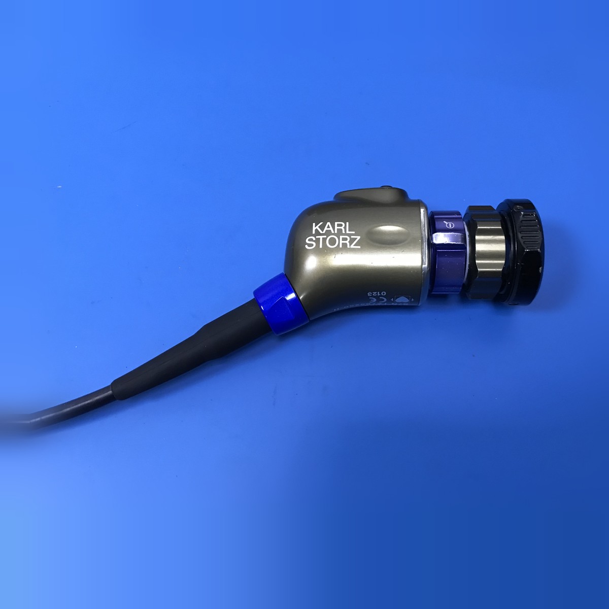
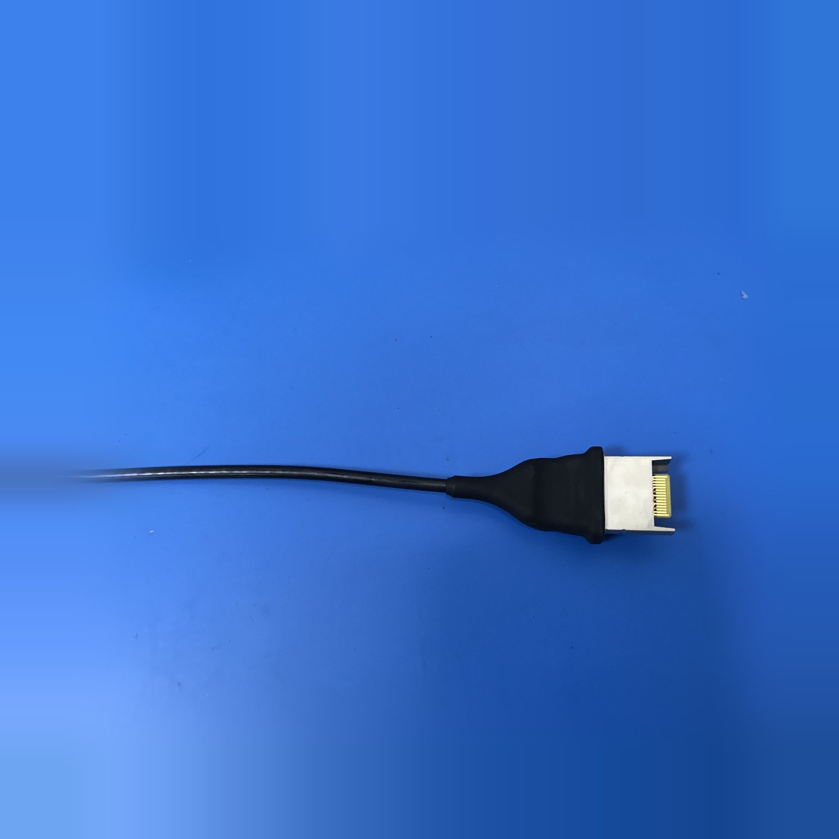
An endoscope camera that drops its image when the cable is moved, then works perfectly on the bench, is one of the costliest faults a service team can misdiagnose. Static tests pass, the processor and light source check out, and the fault is often blamed on the camera head sensor or the video board. In practice the failure is usually mechanical and sits at the cable-to-connector transition: a conductor fractured inside the strain relief, a contact with insufficient normal force, or a shield termination that has lost its path to chassis. This guide explains how to reproduce an intermittent fault deliberately, which measurements actually distinguish a cable defect from a camera head or processor defect, how electromagnetic compatibility and ESD requirements shape the repair, and what to check before a replacement cable assembly is accepted into stock.
Why an intermittent fault passes a static inspection
A continuity test on a stationary cable tells you almost nothing about a fault that only appears under bending, mating, vibration, or temperature change. A conductor can be intact enough to show continuity while a single fractured strand separates when the cable is flexed at the exit boot. A contact can measure acceptable resistance at rest and open momentarily when the connector is rocked. Shielding can be electrically continuous on the bench and still introduce noise when the assembly is routed beside an electrosurgical unit. The defining feature of an intermittent fault is that it depends on a mechanical condition, so the test has to reproduce that condition while the signal is being observed.
The camera cable carries several different circuits in one jacket: high-speed image data from the sensor, low-voltage supply rails, control or button lines, and one or more shield layers. As connector pitch shrinks and micro-coaxial or fine-wire conductors are used, the assembly becomes more sensitive to contact alignment, termination quality, and how the cable exits the housing. That is why the connector transition, rather than the middle of the cable, is the highest-yield place to look.
Reproduce the fault before you replace anything
Set the system up on a live monitor with a stable test image, then work through a fixed sequence of mechanical stresses while watching the picture. Do this before opening the camera head. Record which action produces the fault, because that single observation usually identifies the failed section. The camera system troubleshooting guide covers system-level substitution between head, cable, and processor; the sequence below is the cable-specific part of that work.
| Trigger that produces the fault | Most likely location | What it rules in or out | Confirming measurement |
|---|---|---|---|
| Flexing the cable within 30-50 mm of the connector | Conductor fracture or shield break at the strain relief | Rules in the cable exit; rules out the processor | Continuity on each conductor while flexing, not at rest |
| Rocking or twisting the connector in its socket | Contact force loss, worn plating, or poor mating alignment | Rules in the connector interface | Contact resistance under a defined side load; inspect for fretting |
| Connecting and disconnecting repeatedly | Mating-cycle wear, damaged retention latch or alignment key | Rules in the connector hardware | Count mating cycles; compare retention force to a new part |
| Moving the cable near an electrosurgical unit or RF source | Shield termination or ground-path discontinuity | Rules in EMC integrity, not the image sensor | Shield-to-chassis continuity; inspect 360-degree shield termination |
| Warming the head or cable during a long case | Thermal expansion opening a marginal joint or cracked solder | Rules in a termination or board-level joint | Repeat the test after controlled warming; inspect solder under magnification |
| Fault present regardless of cable position | Camera head sensor, board, or processor side | Rules out the cable assembly | Substitute a known-good cable, then a known-good head |
The last row matters as much as the first. If the image fault is continuous and unaffected by any cable movement, spending time re-terminating a cable is wasted effort. Cable repair is the answer only when a mechanical action reliably changes the picture.
Where EMC and ESD requirements enter the repair
A camera cable is part of a medical electrical system, so its shielding and grounding are safety-relevant, not just a picture-quality detail. IEC 60601-1-2:2014 (fourth edition, with AMD1:2020) is the collateral standard for electromagnetic disturbances. It specifies immunity test levels according to the environment of intended use — professional healthcare facility, home healthcare, and special environments — and according to the ports of the equipment, and it requires manufacturers to define immunity pass/fail criteria for basic safety and essential performance. A repair that leaves a shield floating or a drain wire un-terminated can take a compliant system out of compliance even if the image looks acceptable on the bench.
The general standard IEC 60601-1 covers basic safety and essential performance of the equipment as a whole, including leakage currents and protective measures that a re-terminated cable must not defeat. On the bench, electrostatic discharge is the other controlled hazard: an ANSI/ESD S20.20-2021 ESD control program exists because imaging electronics can be damaged at low discharge thresholds (component sensitivity classes such as 100 V HBM and 200 V CDM are commonly referenced), and camera heads are handled during exactly the operations that generate charge. A grounded workstation, wrist strap, and ESD-safe tools are part of the repair specification, not optional accessories.
Field failures should also be reported, not just repaired. The FDA MAUDE database is the reference point for device-related adverse event reporting in the United States, and recurring cable or connector failures on a single model are worth checking against it. For a repair organisation, the quality-system baseline for traceable incoming parts and controlled rework is ISO 13485:2016.
Isolate cable, head, and processor with a substitution sequence
Substitution is faster than component-level diagnosis when a known-good assembly is available. Work in a fixed order so the result is interpretable: first replace the cable with a verified assembly and repeat the mechanical stress sequence; if the fault remains, substitute a known-good camera head on the same processor; if it still remains, move to the processor and its video input. Do not swap two variables at once. Where a camera head uses a detachable cable, check the connector on both sides of the mating pair, because wear on the head-side socket produces the same symptoms as a cable defect. Socket connectors and board-level receptacles are replaceable parts in their own right — our camera system repair parts category lists them separately from cable assemblies. The optical light guide path is a separate subsystem with its own inspection criteria and is not part of this electrical check.
When a cable is confirmed as the fault, the decision is repair versus replacement. Re-terminating a fine-wire or micro-coaxial assembly by hand requires controlled stripping, crimp or solder control, and a rebuilt strain relief; without those, the repair tends to fail again at the same point. For a high-density camera cable carrying high-speed signals, a complete replacement assembly is usually the more predictable outcome. Keep the failed part tagged with the reported symptom and the mechanical action that reproduced it, so the next identical return is recognised immediately.
Incoming inspection and acceptance checks for replacement cables
A replacement cable assembly should be verified before it is fitted to a customer’s scope and again after the repair. The checks below assume a live test rig with a monitor, a known-good head and processor, and basic electrical test gear. They are written to be recorded, not just performed.
| Check | Method | Acceptance criterion | Record |
|---|---|---|---|
| Part and pinout match | Compare connector shell, pin count, keying, and cable length against the removed assembly | Identical interface; no adapters or forced fit | Part number, camera head model, lot |
| Continuity under flexion | Measure each conductor while flexing the cable at the strain relief through a defined arc | No open circuits or resistance spikes during movement | Pass or fail per conductor |
| Insulation and short check | Measure insulation resistance between adjacent conductors and to shield | No shorts; values within the supplier specification | Measured values, temperature |
| Shield continuity | Verify shield-to-shell and shell-to-chassis continuity end to end | Continuous low-resistance path; 360-degree termination intact | Resistance reading, inspection note |
| Strain relief and exit geometry | Inspect the boot and cable exit; apply a defined gentle pull and bend | No stress transferred to the termination; boot moulded or clamped correctly | Photograph of the transition |
| Mating and retention | Mate and unmate the connector; check latch engagement and alignment | Positive retention, no rocking, no intermittent contact | Cycle count, retention check |
| Live image test | Run a stable test image while repeating the full mechanical stress sequence | No dropout, stripes, or colour shift under any trigger | Bench result tied to serial number |
Note the emphasis on testing during movement. A cable that passes a stationary continuity check and fails the flexion check is the classic intermittent case, and it is the single most common reason a camera returns after an apparently successful repair.
Bench handling that prevents repeat failures
Three habits reduce returns. First, respect the bend radius: camera cables with micro-coaxial conductors do not tolerate a tight bend immediately behind the connector, and the connector exit orientation should follow the routing path rather than forcing a straight plug into a turning cable. Second, control mating cycles: detachable cables that are connected and disconnected repeatedly need a retention mechanism and alignment guidance in good condition, and worn sockets should be replaced with the cable. Third, keep the shield path intact: an inconsistent shield termination creates both mechanical instability and electromagnetic discontinuity at the same time, which is why EMC symptoms and intermittent image loss often appear together.
Tools matter here. A proper camera head repair tool set — the correct spanner for the connector collar, a controlled stripping fixture, and ESD-safe handling — costs far less than a rework that damages a plating or a fine-wire termination. Technicians new to this work can standardise the sequence through the repair training courses, and for confirmation of the correct cable or socket part number for a specific head, use the contact page with the camera head model and connector photograph.
Frequently asked questions
Why does the image return to normal as soon as the scope is on the bench?
Because the fault depends on a mechanical condition — bending, mating, vibration, or temperature — that is absent once the cable is laid flat. Static continuity testing cannot reproduce it. The test has to be run while the cable is being moved and the live image is observed.
Is a cable fault the same as an EMC problem?
Not necessarily, but they overlap. A broken shield termination can cause both intermittent mechanical contact and electromagnetic discontinuity, so noise near an electrosurgical unit and image dropout when the cable is flexed may share one root cause. IEC 60601-1-2 is the reference for the EMC side.
Can a damaged cable be re-terminated instead of replaced?
In principle yes, but a high-density camera cable needs controlled stripping, crimp or solder quality, and a rebuilt strain relief. Without those controls, the repair usually fails again at the same transition. A complete replacement assembly is the more predictable choice for most service teams.