



Blog
Endoscope Camera System Troubleshooting: Image, Light, and Signal Faults

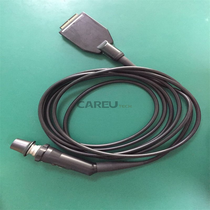
An endoscope camera system fault is almost never a single broken box — it is a chain: camera head, coupler, camera cable, video processor (CCU), light source, light guide cable, and monitor. The fastest path to the right parts order is disciplined substitution: change one link at a time, with known-good components, until the fault moves. Twenty minutes of isolation work routinely separates a camera head sensor fault from a twenty-dollar video cable fault, and the two have very different procurement timelines. This guide walks through the fault domains in signal order, the isolation test for each, and the spares that keep a tower running while a component is out for repair.
The Five Fault Domains and the Substitution Method
Every camera system complaint you will receive falls into one of five domains: image quality (dark, hazy, artifacted, or no image), color (casts that survive white balance), signal (intermittent dropouts and disconnects), light (dim or absent illumination), and power or thermal (shutdowns, resets, fan noise). The order of substitution matters — start with the components that are cheapest and fastest to swap, and work toward the expensive ones. Cables and couplers before camera heads; camera heads before processors; processors before monitors.
| Reported symptom | Fault domain | Isolation test |
|---|---|---|
| No image at all, monitor shows “no signal” | Signal chain | Reseat camera cable at both ends; swap monitor input; test color bars from processor |
| Fixed bright or dark specks in the same position | Camera head sensor | Confirm specks stay fixed when the scope or lens is changed — faults that follow the camera head are sensor faults |
| Image dark even at full light output | Light path | Check lamp hours; inspect light guide cable ends for broken fibers; test with a known-good cable |
| Image intermittent, flickers, or processor drops the camera | Cable or connector | Wiggle test along the cable with the system live; inspect connector pins under magnification |
| Color cast that survives white balance | Color/illumination | Re-white-balance against a proper reference; check lamp age and coupler cleanliness |
| Shutdowns, resets, or loud fan | Power/thermal | Clear vents, verify fan operation, confirm the fault follows the unit and not the mains circuit |
Camera Head Faults
Sensor and optics faults
Dead pixels and fixed debris present as bright or dark dots that never move. The diagnostic question is simple: does the artifact stay in the same screen position when you change the scope or clean the lens? If it follows the camera head across every scope and coupler, the fault is in the head — either the sensor itself or debris on the sensor window. Moisture ingress through a worn seal produces fogging that changes with temperature, a pattern distinct from fixed pixels. Both findings point to a camera head repair, and the head should be pulled from service before intermittent faults harden into total failure mid-procedure.
Coupler faults
Telescope couplers are the cheapest link in the chain and a frequent source of false camera diagnoses. A coupler with internal fogging, a scratched lens, or a loose clamping mechanism produces hazy or unstable images that disappear when the coupler is swapped. Clean and inspect the coupler before any decision that involves the camera head, and always check the telescope eyepiece for the same contamination class.
Light Source and Light Guide Faults
Dim images are usually light-path faults, not camera faults. A peer-reviewed review of video endoscopy system troubleshooting makes the mechanism explicit: as the number of intact fibers in the light-carrying bundle decreases, the light reaching the scope tip decreases, and the monitor image degrades even though the camera is healthy. Inspect the light guide cable ends against a bright background — broken fibers appear as dark spots in the end face — and check the lamp hour counter before assuming lamp failure. Xenon and halogen lamps fade with hours and are replaced on schedule, not on the day they die. The same review adds a safety point worth posting in every procedure room: a fiber-optic cable disconnected from the scope but left on the surgical field remains hot enough to be a fire hazard, so lamp and cable faults should be corrected, not worked around.
Cable and Connector Faults
Camera cables are the highest-flex components in the tower and fail more often than the boxes they connect. The classic presentation is an image that flickers when the cable is moved, or a processor that intermittently reports the camera as disconnected. With the system live, flex the cable section by section and watch the monitor; a fault that appears at one section localizes the break. Then power down and inspect both connectors under magnification for bent pins, cracked strain reliefs, and contamination in the sockets. Replacing a cable is fast and inexpensive; replacing a camera head because a cable fault was misdiagnosed is neither.
Handle the connectors as precision parts during every reprocessing and setup cycle: never force a connection, never support the camera head by its cable, and keep strain reliefs free from cart clamps. Most intermittent faults in this domain trace back to chronic mechanical abuse, not component defects.

Processor and CCU Faults
Once the camera head, cables, and light path are cleared, the processor is the remaining active component. Processor faults divide into settings and hardware. Settings faults — wrong image processing mode, brightness limits, output format mismatches with the monitor — cost nothing to fix and should be ruled out first by resetting to defaults and verifying the video output mode. White balance problems fall in this class: the classic nursing literature on video endoscopy troubleshooting notes that white balance must be performed correctly for the processor to transmit accurate colors, and that the monitor must be color-balanced to display them — two separate calibrations that teams often collapse into one. Hardware faults in the CCU — output boards, power supplies, cooling fans — present as missing outputs, thermal shutdowns, or dead pixels that stay fixed across every camera head. A processor that fails with a known-good camera head goes to the bench.
Monitor and Video Output Faults
Monitors are the last link and the easiest to clear: swap the input cable, then test the suspect monitor against a known-good one. Two monitor-specific faults deserve attention. Persistent lag between the true image and the display is often the monitor’s own image processing — consumer display features add latency that medical-grade monitors avoid — and should be measured, not assumed, before any camera or processor work is ordered. And single-output failures (image on one monitor but not another) point to the processor’s output stage or the output cable, not the camera chain.
What to Stock So One Fault Does Not Stop the List
Camera system availability is a spares policy, not a repair skill. The table below lists the components worth holding at bench level, the faults each one covers, and the stocking logic.
| Spare held | Faults covered | Stocking logic |
|---|---|---|
| Light guide cable | Dim image, broken fibers, cable crush | Inexpensive; the most common light-path fault; keep one per connector type in use |
| Camera head video cable | Flicker, intermittent disconnect, no signal | Covers the highest-flex component; verify connector type per camera family |
| Video output cable (per output format) | No signal to one monitor | Cheap; isolates processor output faults during a case |
| Spare coupler | Hazy or unstable image | Fastest false-fault to clear; also serves as a test fixture |
| Lamp module (xenon systems) | Lamp end-of-life | Track lamp hours and replace on schedule rather than at failure |
For the repair bench itself, compatible camera system repair parts — camera heads, cables, light guide cables, and coupler components for Olympus, Storz, Stryker, and Wolf systems — reduce the substitution loop to parts you already own. The shop-by-brand catalog lists parts by original system, which shortens compatibility checks when a tower mixes generations. Related fault-isolation methods for the scopes themselves are covered in the bending section diagnosis guide, and camera head repair technique is part of the hands-on repair training curriculum.
Documenting the Fault Before It Leaves the Bench
Record the complaint as reported, the substitution sequence, and the component the fault followed — the complaint, cause, and resolution that a repair vendor needs to quote accurately. For camera heads and processors that repeatedly fail, check the FDA’s MAUDE adverse event database for reported patterns on the same model before approving a third rebuild of the same unit; a model with documented systemic faults is a replacement candidate, not a repair candidate. And when you source replacement camera parts from an independent supplier, verify that the supplier works to a documented quality management system such as ISO 13485, because camera head repairs involve sensor alignment and sealing work where process control is the difference between a repair and a delayed failure.
Key Takeaways
Substitute in signal order — coupler and cables first, camera head second, processor third, monitor last — and change one link at a time with known-good parts. Dark image is a light-path fault until proven otherwise; fixed artifacts are camera head faults until they move. Stock the cheap links so a fault never stops the procedure list, document every substitution result, and escalate to bench repair only when the isolation test has already named the component. For camera head, cable, and light guide parts for the major endoscopy brands, contact the CareUTech team with your model and fault description.
Sources: Marousky RT, Troubleshooting the video endoscopy system, Todays OR Nurse (1993); IEC 60601-1 medical electrical equipment standard; FDA MAUDE database of medical device reports; ISO 13485:2016 for supplier quality management requirements.