


Blog
Light Guide Cable Sourcing: Compatibility, Light Loss, and Incoming Inspection


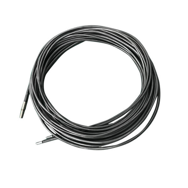
A dim endoscope image is usually blamed on the light source or the processor, but the part most often responsible is the cheapest one in the chain: the light guide cable. Whether it is a standalone fiber optic cable between light source and rigid scope, or the bundle carried inside a flexible scope’s light guide tube, the cable degrades mechanically over its life and loses output before anything in the imaging chain misbehaves. This guide covers how light is lost, how to measure the loss so you replace the right part, and the compatibility variables to verify before ordering a replacement light guide cable.
Where the Light Actually Goes
Illumination losses in endoscopy are larger and more structural than most buyers assume. In a photometric analysis of commercial rigid endoscopes published by researchers at the Institute of Applied Optics and Precision Engineering (Gaertner & Belloni, Current Directions in Biomedical Engineering, 2018), the overall illuminance efficiency of the illumination optics measured below 20%, and ray-tracing identified the interface between the fiber optic cable’s coupling cone and the scope’s internal fiber bundle as the dominant loss point — partly because the core material of the bundle covers only about 65% of the bundle surface, with cladding and adhesive absorbing the rest, and partly because the cable’s measured angular light distribution (a half cone angle of 36° in their tests) must match the coupling geometry or light spills outside the acceptance cone.
The practical takeaway for a repair shop or a biomed department: the illumination chain is a matched system — light source, cable end-face, cable connector geometry, scope coupling, and internal bundle. Any replacement part that changes one link, such as a cable with a different numerical aperture or a tip connector that does not seat to the same depth, shifts where the losses land even if every individual component “works.”
Four Failure Modes of Light Guide Cables
- Fiber fracture. Repeated flexing, kinking, or crushing of the cable breaks individual fibers permanently. Output falls in proportion to the fibers lost, and broken fibers are visible as dark points on the lit connector face. Damage accumulates from handling — cart crush, tight coiling, doors on cables — not from procedure count alone.
- End-face contamination and burn. Residue or deposits on the polished connector face absorb light and char under the concentrated output of the light source, cutting transmission immediately and sometimes severely. Unlike fracture, this is reversible: clean and re-inspect before ordering anything.
- Sleeve damage. A split or worn protective sleeve exposes fibers to the mechanical loads that cause fracture, and typically shows output loss at specific bend angles first.
- Connector mismatch. A tip that does not match the light source port — wrong diameter, wrong seating depth, wrong keyway — loses light at the coupling or, worse, overheats. This is a compatibility failure, not a wear failure, and it shows up right after a wrong-part installation.
Measuring Light Loss Before You Order
The cheapest diagnostic is the connector face itself. Power the cable from the light source at a fixed setting and inspect both end-faces under magnification: scattered dark points on a lit fiber field indicate broken fibers; a uniform yellow-brown film or charred spot indicates contamination or burn; a clean face with adequate output means the cable is not the problem. Then compare output against a known-good scope or cable on the same light source and settings — a relative comparison removes the light source from the equation entirely.
For departments that want numbers, the reference points come from a multi-center evaluation of optical degradation published in 2025, which analyzed long measurement series of rigid endoscopes and describes working rejection thresholds of 70% light transmission and 30% fiber transmission relative to new — meaning scopes in that dataset were typically pulled from service once transmission fell to those fractions of their initial values. The same study found practice varies: some endoscope types stayed in use at light transmission near 55% where replacement was costly and clinical need was high, which is why the authors recommend an entrance measurement when procuring new or repaired scopes, so each device has its own baseline rather than an assumed number.
Set your own policy the same way: record the transmission of each new cable and scope at intake, and trigger replacement review when a cable falls below your chosen fraction of its own baseline, rather than adopting any single universal percentage as a hard rule.
| Observation on the bench | Diagnosis | Correct action |
|---|---|---|
| Clean connector face, output matches reference cable | Cable is healthy | Investigate light source lamp, filter, or scope-side coupling instead |
| Uniform film or charring on end-face; output recovers after cleaning | End-face contamination or burn | Clean with optical-grade IPA and lint-free wipes; re-check; replace only if char persists after proper cleaning |
| Scattered dark points across the lit face; output low | Fiber fracture from handling | Replace the cable or bundle; review handling and coiling practice |
| Dense dark cluster at one zone of the face | Localized crush or kink damage | Replace; inspect sleeve along the cable for the damage point |
| Dim only when seated in a specific scope or port | Coupling/geometry mismatch | Verify connector type and seating depth against the port specification before blaming the cable |
Compatibility Variables to Verify Before Ordering
Light guide cables and bundles are not generic. Two cables that look identical and fit the same ports can deliver noticeably different light if their bundle diameter, fiber packing, or coupling geometry differ. Before ordering, verify each variable below against the scope model and the light source it will run on — the endoscope standard ISO 8600-1:2025 requires manufacturers to state optical and connector characteristics in the instruction manual, so the controlling documents are the manuals for the specific models on your floor.
| Variable | Why it matters | How to verify |
|---|---|---|
| Light post / tip connector type | Determines seating depth, O-ring seal, and light capture at both ends | Match the stamped part number on the original tip (e.g., an OEM 495-type tip); confirm against the scope service manual |
| Bundle diameter and active area | Smaller active area captures less light at the coupling; mismatch shifts loss to the interface | Measure the tip’s glass bundle under the microscope; compare with the removed original |
| Cable length | Longer cables lose more light; a longer “equivalent” cable can dim a marginal system | Match the original length; note it in the RFQ |
| Source-side adapter | Must match the light source port family and seat at the same depth | Test-fit on the actual light source before accepting the part |
| Sleeve and sterilization rating | Some cables tolerate autoclave cycles, others degrade; wrong sterilization kills fibers early | Confirm the rated sterilization method from the supplier in writing |
| Bend radius limits | Minimum bend radius protects fibers; exceeded once, loss is permanent | Follow the supplier’s stated handling limits; train staff on coiling diameter |
RFQ Inputs That Get the Right Cable Shipped
A cable RFQ that states only a brand and a length invites a near-miss part. Include: scope model (or light source model for standalone cables), the stamped tip connector marking, bundle diameter if measured, original cable length, sleeve type and color if it matters to your identification scheme, sterilization method in use, and — if you have the equipment — the transmission of the removed cable, so the supplier knows what performance you expect the replacement to restore. Suppliers who work to a quality system aligned with ISO 13485:2016 can trace cable lots and verify outgoing inspection; ask for it when the volume justifies it.
Incoming Inspection Checklist
- Tip connector stamps match the RFQ and seat correctly on both ports, with no play.
- Both end-faces are clean and polished under magnification, with no chipping at the ferrule edge.
- Output at a fixed light source setting matches or exceeds the removed cable’s baseline.
- Sleeve intact along the full length; no kinks from shipping; coil diameter respected.
- Sterilization rating documented before the cable enters reprocessing.
- Baseline transmission recorded in your equipment log for future comparison.
Handling Rules That Protect the Replacement
A new cable inherits the failure modes of the old one unless handling changes. Coil at a generous diameter — never fold or hang a tight loop over a hook. Cap both end-faces during transport and storage. Keep cables out of equipment drawers where they get crushed under scopes. Clean end-faces after each reprocessing cycle, and inspect the face weekly: catching contamination early costs a wipe; catching it late costs a cable. For video systems, cable-side dimming interacts with camera faults, so run the triage sequence in our camera system troubleshooting guide before replacing optics. Standalone cables and bundles for rigid scopes are listed in the rigid endoscope parts section, camera system cables in the camera system parts section, and bench tools for end-face work in the repair tools section. If you are unsure which bundle matches your scope model, send the stamped tip markings through the contact page and we will confirm compatibility before quoting.
Frequently Asked Questions
Can a broken light guide bundle be repaired?
Localized fiber fracture inside a bundle is not repairable — broken fibers stay broken. What is repairable is everything around the bundle: end-face polishing, sleeve replacement, and tip re-mating. A repair shop can restore a cable with an intact bundle and a damaged end or sleeve; a cable with a dense fracture cluster is a replacement.
Why does my image look dimmer on one scope than another with the same cable?
The coupling interface between cable and scope is a major loss point, and it varies by model. Two scopes on the same cable can produce different brightness purely from coupling geometry and internal bundle area. Compare each scope-cable pair against its own recorded baseline rather than across pairs.
What transmission level justifies replacement?
Published multi-center practice has used rejection thresholds around 70% light transmission relative to new, with variation by brand and clinical need — some departments accept lower values where replacement is costly. Record your own baseline at intake and set your threshold as a fraction of it; avoid adopting any single number as a universal rule.