


Blog
Ultrasound Probe Repair: Cable, Lens, and Crystal Failures

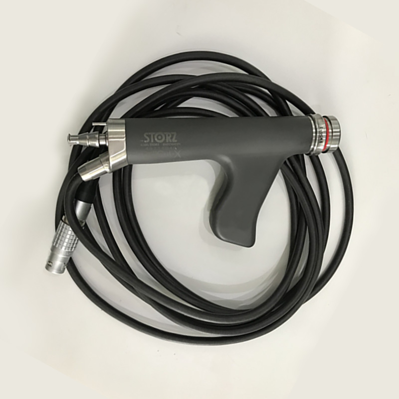
Three fault classes dominate ultrasound probe failures: the cable and strain relief, the acoustic lens, and the piezoelectric array. In a survey of 676 transducers from seven manufacturers in daily clinical use across 32 hospitals, 39.8% carried a detectable fault — delamination of the lens accounted for 26.5% of probes and cable breaks for 8.4% — while faults originating from the piezoelectric elements themselves were comparatively unusual. For a repair operation, that distribution is good news: it means most probe faults are mechanical and repairable, and a structured diagnosis before dispatch tells you whether you are paying for a strain relief re-termination, a lens replacement, or an array rebuild. This guide covers the fault classes, the field tests that separate them, and the acceptance criteria that protect you when the repaired probe comes back.
How Often Ultrasound Probes Actually Fail
Probe failure is not an edge case — it is routine fleet management. Three published datasets frame the scale. In the 676-transducer survey by Mårtensson and colleagues, 39.8% of probes in daily use exhibited a transducer error. A UK multicentre survey of 219 probes across 12 centres by Dudley and Woolley found 37% classified as faulty, with 13% judged not fit for clinical use and a further 24% fit for purpose but requiring repair or monitoring; fault rates varied widely between sites, from near zero to over half of the fleet, which points to handling practice as a decisive variable. And a probe-repair assessment study citing the published literature reports annual probe fault rates of 14–27%. The practical consequence: a department running ten probes should expect one to three probe faults per year, and a spares-and-repair workflow pays for itself quickly.
One more number from the UK survey is directly relevant to repair planning: 23% of faults were found by physical inspection alone. You do not always need an electronic tester to start the diagnosis — trained eyes and hands catch a quarter of the problems before anything is connected.
The Three Dominant Fault Classes
Cable and strain relief
The cable is the most abused part of the probe: it is rolled over by cart wheels, clamped in drawers, wrapped tightly around the probe handle for storage, and flexed thousands of times at the strain relief where cable meets probe housing. Industry guidance on probe damage reports that a Swedish study attributed roughly 30% of probe failures to the cable. Typical presentations are intermittent signal loss when the cable moves, visible cracks in the strain relief, and damaged grommets at the connector end. Cable re-termination and strain relief replacement are among the most common and most cost-effective probe repairs — provided the array itself is healthy.
Lens
The acoustic lens is the soft polymer face that contacts the patient, and it fails in two main ways. Delamination — the lens and matching layers detaching from each other — is the single most common probe fault in the published data, and it shows up on imaging as a broad disruption of the reverberation pattern or as local image degradation. Mechanical damage is the second mode: gouges, scratches, and punctures, frequently from needle-guided procedures where needles contact the lens surface. Manufacturer guidance notes that studies attribute 30–70% of probe faults to the lens. Lens faults also carry an infection-control consequence — a cracked or gouged lens can harbor reprocessing residue — so a damaged lens is a remove-from-service finding, not a monitor-and-continue finding.
Array elements and crystals
Faults in the piezoelectric elements themselves are the least common class, but they are the ones that silently degrade diagnostic quality. A few dead or weak elements present as dropout — dark vertical stripes in the image — that sonographers gradually learn to work around rather than report. The in-air reverberation test is the standard field screen: with the probe held in air, healthy elements produce a series of horizontal reverberation bands, and dead or weak elements interrupt those bands with vertical dark stripes. Electronic probe testers go further, measuring each element’s pulse-echo amplitude and capacitance individually and mapping dropout directly. In the 676-transducer survey, every probe was tested on an electronic tester, which is how the fault distribution was established at all — element faults are largely invisible without one.
| Symptom | Most likely fault class | Field check before dispatch |
|---|---|---|
| Intermittent signal loss when cable moves | Cable break at flex point | Flex test while imaging; inspect strain relief and grommets |
| Visible crack, gouge, or puncture on face | Lens mechanical damage | Visual inspection; remove from service if seal integrity is doubtful |
| Broad band of image degradation | Lens delamination | In-air reverberation test; look for disrupted bands |
| Dark vertical stripe(s) in the image | Dead or weak elements | In-air reverberation test; confirm with electronic tester |
| No recognition by the scanner | Connector or internal cable fault | Inspect connector pins; test probe on a second scanner |
| Probe fails after cleaning cycle | Chemical damage to lens or housing | Review cleaning agents against manufacturer compatibility list |

What the Evidence Says About Repair Quality
Probe repair has a specific failure mode of its own: the repair that restores the image but degrades the probe’s acoustic performance. Dudley and Woolley’s assessment of repaired probes in clinical circulation found that of 3,212 used probes examined, 21 carried repairs involving functional parts — and of those, 9 were incorrectly wired and 11 contained non-OEM replacement arrays. In one documented case, a third-party replacement array reached only 63% of the sensitivity of the OEM array, and sonographers judged the resulting images non-diagnostic. Relensed probes and cable re-terminations fared better when performed with correct materials, but the study’s conclusion is blunt: repairs involving functional parts need a more comprehensive test suite than a standard electronic report to demonstrate that the probe still performs to specification.
Regulatory definitions draw the same line. UK MHRA guidance distinguishes a repair, which restores the device to working condition without changing its performance characteristics, from refurbishment or remanufacture, which change what the device is and can require fresh approvals. When you commission a probe repair, that distinction is yours to enforce: the probe that returns should perform as the original did, with test data to prove it.
Acceptance Criteria When the Probe Comes Back
Repair vendors typically provide an electronic probe test report, and the industry-standard acceptance line is individual element sensitivity consistently above 75% of the mean with uniform capacitance. That is a useful floor, but the repair-quality study notes what those reports usually omit: comparison of sensitivity and capacitance with the OEM’s original values, plus pulse width, center frequency, and bandwidth data that reveal departures from original performance. Before you accept a repaired probe, require the test report and check it against the table below.
| Acceptance item | What to look for | Why it matters |
|---|---|---|
| Element sensitivity map | No element below 75% of the mean; no clustered dropout | Catches weak arrays and localized damage |
| Capacitance uniformity | Uniform values across elements | Detects delamination and bonding faults early |
| Frequency and bandwidth data | Values within the OEM specification for the probe model | Reveals non-OEM array substitution, not visible in amplitude alone |
| Before/after comparison | Test data from before the repair where available | Distinguishes pre-existing faults from repair-induced changes |
| Physical inspection | Lens surface intact, strain relief stable, seal clean | 23% of field faults are visible to inspection alone |
| Imaging verification | In-air reverberation bands clean and uniform | Confirms clinical imaging performance on your own scanner |
Preventing the Damage in the First Place
The fault data points to handling and cleaning as the controllable variables. The UK survey found fault rates significantly higher among probes used outside imaging departments — 67% versus 35% — attributing the difference to less controlled environments. Manufacturer guidance is specific about the common mechanisms: avoid hanging probes by their cables, stow cables loosely rather than wrapped tight, keep cart wheels away from cable paths, and clean with approved materials using wiping rather than rubbing actions. Disinfectant wipes containing more than 70% alcohol can damage the lens, cables, and connectors, and one cited study showed image-quality degradation from wiping probes with 80% ethanol. A five-minute in-service on handling and a posted cleaning-agent compatibility list are the cheapest probe-fault prevention available.
Stocking and Sourcing for Probe Fleets
For departments and repair companies that manage probe fleets, compatible ultrasound probe parts and accessories — cables, strain reliefs, lens materials, connector components, and replacement probes — keep the most common fault classes fixable without long vendor queues. Documented repair cases show the fault classes described here as they arrive at the bench, which is useful calibration for in-house triage. The relevant repair tools — for cable re-termination, lens work, and connector service — and the hands-on equipment repair training program cover the same fault classes for teams building probe repair capability in-house.
Key Takeaways
Test before you dispatch: visual inspection, the in-air reverberation test, and an electronic probe tester separate the three dominant fault classes and set the repair scope correctly. Expect one to three probe faults per year for a ten-probe fleet, weight your spares toward cable and lens consumables because that is where the failures are, and enforce acceptance testing on returned repairs — element sensitivity above 75% of mean, uniform capacitance, and frequency data within OEM specification. A repair that cannot document its performance is a risk, not a saving. For quotes on ultrasound probe parts, cables, and compatible replacement probes for Toshiba, GE, Philips, and other major systems, contact the CareUTech team with your probe model and fault description.
Sources: Mårtensson M, Olsson M, Segall B, Fraser AG, Winter R, Brodin LÅ, High incidence of defective ultrasound transducers in use in routine clinical practice, European Journal of Echocardiography (2009); Dudley NJ, Woolley DJ, A multicentre survey of the condition of ultrasound probes, Ultrasound (2016); Dudley NJ, Woolley DJ, Assessment of Repaired Diagnostic Ultrasound Probes, Ultrasound in Medicine and Biology (2019); Nanosonics guidance on common types and causes of probe damage (2023).